
Solar Rooftop System provides following technical benefits:
- Utilization of available vacant roof
- Low gestation
- Lower transmission and distribution
- Improvement in the tail-end grid voltages andreduction of system
- Loss mitigation by utilization of distribution network as a source of storage through net
- Long term energy and ecological security by reduction in carbon emission
- Abatementof about 60 million tonnes of CO2 per year over its life cycle;
- Better Management of daytime peak loads by DISCOM/ utility;
- Meeting of the renewable purchase obligations (RPOs) of obligated entities which are targeted at 8% of electricity consumption;
- Minimal technical losses as power consumption and generation are co-located.
A solar panel (also solar module, photovoltaic module or photovoltaic panel) is a, connected assembly of solar cell. The solar panel can be used as a component of a larger photovoltaic system to generate and supply solar power in commercial and residential applications. Each panel is rated by its DC output power under standard test conditions, and typically ranges from 100 to 450 watts. The solar cell efficiency of a panel determines the area of a panel given the same rated output an 8% efficient 230-watt panel will have twice the area of a 18% efficient 340-watt panel. Because a single solar panel can produce only a limited amount of power, most installations contain multiple panels. Electrical connections are made series to achieve a desired output voltage and/or parallel to provide a desired current capability. Separate Diode may be needed to avoid reverse currents, in case of partial or total shading, and at night. Reverse currents waste power and can also lead to overheating of shaded cells. Solar cells become less efficient at higher temperatures and installers try to provide good ventilation behind solar panels.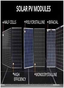
Intensity of the sunlight will be maximum utilized when incident irradiation is perpendicular to PV module, hence Orientation and tilt of these panels are important design parameters, as well as shading from surrounding obstructions.
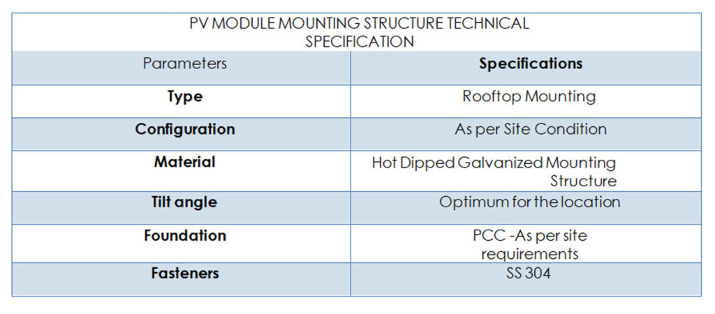
- Structures will be made of galvanized mild steel/ aluminum based on site soil and wind load parameter Suitable number of Array frames will be provided based on the design and site
- The array frames proposed for the site would typically utilize maximum sunlight with a different tilt angle capability and these array frames will be corrosion
- The array frames are designed for simplicity, low cost and ease of installation at The Structure consists of a set of components that can be managed and mounted in the place where the installation is going to be realized. These structures are designed to survive adverse weather conditions with minimum maintenance. The structure will be supplied with all members to be compatible allowing easy installation at the site.
The multi-strand Copper/Aluminum cables will be used for interconnection of electrical components like PV Modules, Junction boxes, distribution Boards & Inverter. All the cabling will be carried out as per the MNRE standards. The size and length of the cable will be selected such that there will be minimum voltage drop and the effect of temperature is minimum.
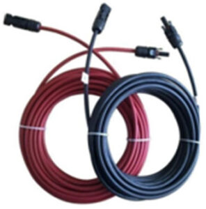
The size of cables will be selected considering the short circuit current that can flow through the cables. Cables will be housed inside PVC conduit pipe for unarmored cables and all cables will be underground cabling with the cable trench at a minimum depth of 80 CM.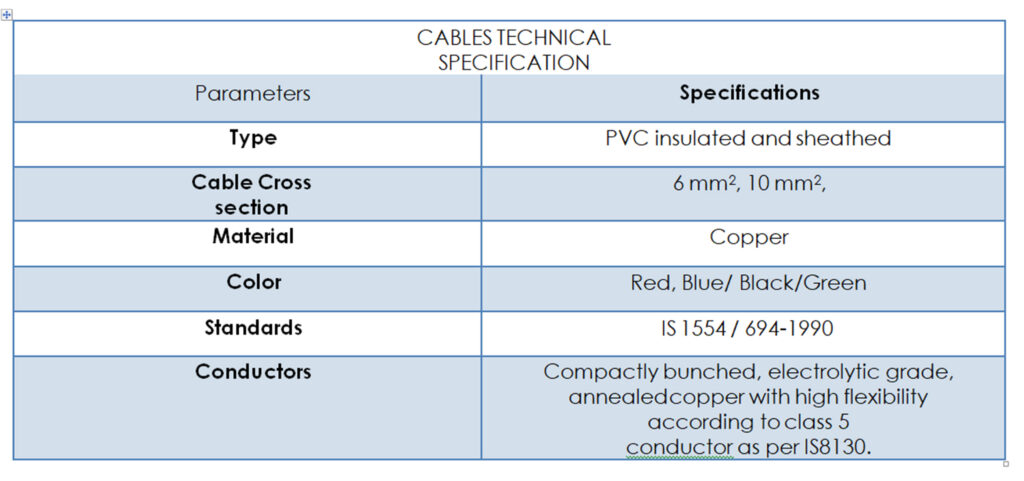
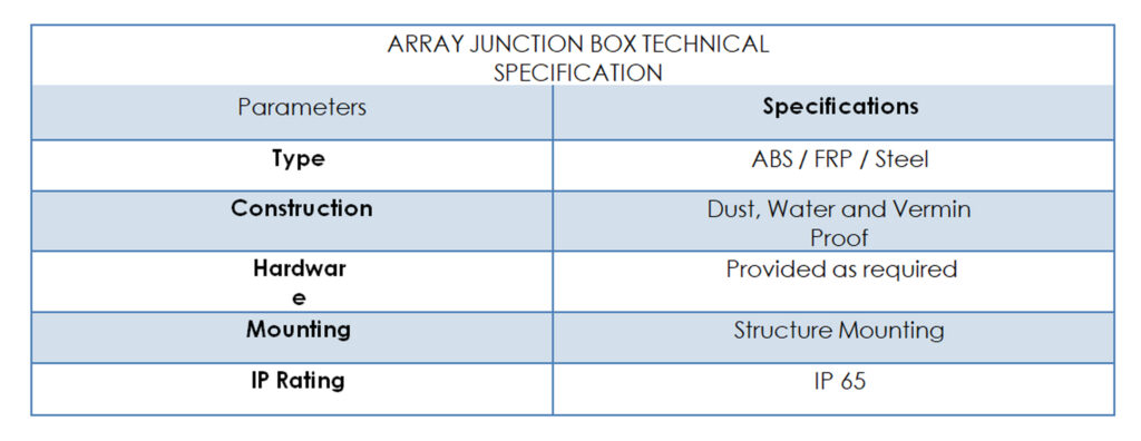
The array junction boxes are utilized to connect the various strings of the Solar Photovoltaic Array electrically and protections devices will be incorporated in the junction boxes. The junction boxes in use are of impeccable quality and have been proven by some of the leading quality testing institutes in the world. Some of its features are singled out below:
- High level terminals allow wiring to be done quickly
- Ample space for connection
- Self-sealing membrane entries
- Junction boxes are outstanding for the design, ample wiring space and rugged
- Impact & fracture resistant
The junction boxes will be mounted on pole of array support structures. It will have proper locking mechanisms. Suitable marking will be provided on the lugs for easy identification. The junction boxes will have suitable cable entry points fitted with the cable glands. AJB is provided to combine the string form PV array. The AJB will have MOV and Fuse for protections propose. The AJB will be made of non-metallic enclosure with IP 65 outdoor rating.
Solar inverter converts the DC power to AC power to facilitate feeding into the grid. The inverter is the most complicated part of the PV system. It has to act as the interface between the PV array and the Grid. As the PV array output varies with the solar radiation and the inverter has to cope with the same. The inverter has protection features for overvoltage, under voltage, surge etc. The inverter is provided with the features for logging and display of parameters related to Plant operation & faults etc. The inverter will use MPPT to maximize energy drawn from the array. The MPPT will be microprocessor based to minimize power losses. The output from the inverter will be fed to the AC distribution Board.
The main functions carried out by the inverter are as follows:
- Converting the incoming DC received from PV modules into AC with suitable power quality The inverter produces sinusoidal AC wave forms with low harmonic distortion
- The inverter also has to act as a protective device of the It needs to trip out if the voltage, current or frequency goes outside acceptable ranges.
- Pulse width modulation is used to generate a wave form as near as possible to a sine High-speed switching device are used to generate pulses of the devices mainly use for inverter circuitry.
- Inverter efficiency is expected to be about 98% mainly by deploying new switching
Low Voltage AC Board (LV ACDB) panel shall be provided between load and inverter. The metal enclosed outdoor ACB panels shall be dust tight and damp proof with outdoor application IP rating. LV ACB panel with microprocessor-based release/thermo magnetic ACB module having following inbuilt protection functions:
- Long time protection
- Short time protection
The earthing of all outdoor equipment & provision of associated earthing systems, electrodes & connections will be as per latest IEEE and IS 3043 standards Earth electrodes will be provided throughout plant areas along with the main earth grid. The number of earth electrodes will be taken so as the total earth grid resistance is less than 1 ohm. The earth electrodes will be provided in earth pits. The earth pit will be of two types –treated with earth links & untreated. The main buried grid conductors will be connected to all the earth electrodes to form a total earth grid. Galvanized steel flats will be used as per approved design.
The frames of all electrical equipment & structural work will be earthed by connection to the earth grid by branches of same cross-sectional area of earth grid
Lightning protection will be as per IS Standards and IE rules.
Suitable for Solidly Earthed system neutral system and 10kA
* The arrestor shall be capable of spark over on server switching surges and multiple strokes.
The lightening arrestor shall be capable of discharging over voltage occurring during switching of unloaded
* Surge counters with insulating base for connection, supporting insulator and necessary hardware shall be provided.
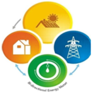
The way how electricity is billed strongly influences profitability of the PV investments. To fully harness the benefits of the investments, the final user should be able to make the most of metering system.
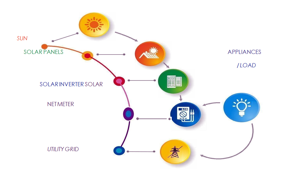
Net metering systems are primarily aimed at providing an opportunity to consumers to offset their electricity bills, wherein a single meter records both import of conventional energy from distribution grid and export of solar energy into distribution grid. Thus, net metering allows the final user to credit produced energy in the grid and is also promoted as a preferred option.
Taking the above case, if the customer’s consumption is at an average of units 360, average monthly unit cost as per slab rate is 7.5-00, so consumer can be saving every month 2,700-00
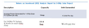
Therefore, from the above Consumption Analysis we can understand that the customer will incur Electricity Bill for their consumption on DISCOM Grid enabled energy system at an average including All quarters of Seasons after minimum Charges to DISCOM is,
| 1 Month | | 2,700 -00 |
1 Year
ROI Within 3 Years
ROI for 25 Years |
| 32,400-00
1,15,900 -00
8 ,10,000 -00 |
Cost to end user in DISCOM Grid enabled energy consumption for 4 Years would nearly be equaling the capital invested by customer in ON GRID Roof Top Solar PV System. Thereafter year onwards customer shall experience near to zeroed bill with doubled ratio of ROI in terms of the unitized electric power and also exported electric power to grid storage benefit at DISCOM even after their regular electricity consumption.
Customer will become Self-sufficient in generating power and become freed from electricity bills with less maintenance for the 4 Years and there after until another 20 Years the end user can utilize generated power with a bare minimum maintenance cost along with an average unitage cost lesser than regular DISCOM unit charges thereby client gains benefit more than the ROI Factor for 25 Years period.